
IMAGING, MICROSCOPY AND SPECTROSCOPY

For optical coupling of the various CCD and ICCD cameras, several adaptors such as C-monunt, F-mount, or customized (for various microscopes, imaging spectrographs etc.) are available. Please contact for more details.

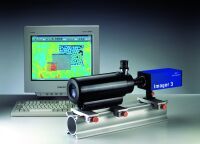 for diffraction limited resolution imaging at high magnification and long working distances Based on high speed, high resolution Cassegrain catadioptic design. for diffraction limited resolution imaging at high magnification and long working distances Based on high speed, high resolution Cassegrain catadioptic design.
QM 100: 1.5µm @ 15 cm; QM 1: 3µm @ 55cm; DR1: 12µm @ 300cm

TauTec offers Dual/Quad View Image splitters from Optical Insights Inc. for simultaneous dual or quad channel imaging on the same CCD cameras.
We also offer optical setups for simultaneous multichannel imaging using multiple detectors (PMTs or CCD cameras).

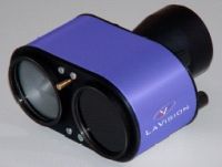 The Image Doubler is a stereoscope and provides the projection of an image pair onto one camera. Filters can be inserted for each image separately. The Image Doubler is a stereoscope and provides the projection of an image pair onto one camera. Filters can be inserted for each image separately.

For spectral imaging, the CCD/ICCD cameras can be conveniently coupled to imaging spectrographs. TauTec offers and supports imaging spectrographs from different vendors.

 8 position filter wheel 8 position filter wheel
accomodates standard 25mm filters
< 65ms switching time between adjacent positions
remote control via RS 232 interface
simple control, driver for most OS available adapters for most standards available (c-mount, dovetail, ...)

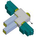 accomodates up to 4 PMTs accomodates up to 4 PMTs
separates up to 4 wavelengths by dichroic mirrors and edge filters
simple load/unload mechanism for dichroics and filters
integrated manual shutter
fits to most commercial microscopes
adapters for most standards available (c-mount, dovetail, ...)

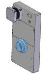
 accomodates up to 3 detection devices accomodates up to 3 detection devices
3 configurations adjustable
top ccd
rear ccd and top ccd (light can be separated with dichroic or beam splitter)
side port (can be equipped with PMT Detector Block)
fits to most commercial microscopes
adapters for most standards available (c-mount, dovetail, ...)

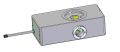
 This compact unit is designed for the critical timing adjustment of fast instruments. It will delay an arbitrary input signal over an adjustable range of 20 ns in 25 ps steps and consists of a set of switched 50 ohm calibrated delay lines together with a controlling microcomputer. These is no inherent jitter. The rise time is about 500 ps and has a high voltage capability for short pulses. The delay is set from the front panel or from an RS 232 remote control interface. Current delay setting is shown on LCD display with relative or absolute delay mode. The delay is achieved by the switching in and out of sections of delay line by matched relays. The unit will be useful in such applications as the adjustment of timing of fast cameras and triggering or pulse shaping in laser systems. This compact unit is designed for the critical timing adjustment of fast instruments. It will delay an arbitrary input signal over an adjustable range of 20 ns in 25 ps steps and consists of a set of switched 50 ohm calibrated delay lines together with a controlling microcomputer. These is no inherent jitter. The rise time is about 500 ps and has a high voltage capability for short pulses. The delay is set from the front panel or from an RS 232 remote control interface. Current delay setting is shown on LCD display with relative or absolute delay mode. The delay is achieved by the switching in and out of sections of delay line by matched relays. The unit will be useful in such applications as the adjustment of timing of fast cameras and triggering or pulse shaping in laser systems.
Specifications:
- Delay Range 20ns
- Intrinsic delay 6.5ns
- Delay Step 25ps or multiples thereof
- Interstep error +- 0.5 steps
- Jitter effectively zero, mechanical device
- Impedance 50 ohm
- Voltage Handling DC 30V, 1.5kV/ns
- Control Fully functional manual control via front panel keys
- Remote control RS 232, 9600 baud, ASCII commands
- Display LCD Display of status and functions

 Delay Generator: The delay generator provides pulse delay times from the ns range to the µs range with a delay resolution down to 2.5 ps. Its low jitter and short intrinsic delay makes it useful for a variety of triggering and pulse shaping applications. Delay Generator: The delay generator provides pulse delay times from the ns range to the µs range with a delay resolution down to 2.5 ps. Its low jitter and short intrinsic delay makes it useful for a variety of triggering and pulse shaping applications.
All delay and trigger parameters are controlled via the Windows compatible software. For user programmed special applications a DLL library of the basic module functions is available.
Specifications:
- Delay Resolution: down to 2.5 ps
- Jitter: min. 10 ps or 0.05 % of Delay Range
- Delay Range: 10 ns to 100 µs
- Input Trigger: 50mV to 2V
- Output: TTL, ECL or NIM
- Output Pulse Width: 2 ns to 2000 ns
- PCI Plug-In Interface
- Windows compatible user interface

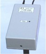 The compact optical trigger unit has been designed to provide stable trigger pulses from optical pulses with unstable amplitude.The principle of operation is as follows: the photodiode converts the input optical pulse into an electrical signal. The electrical pulse is then shaped by a linear electrical network to yield a bipolar zero-crossing pulse. The zero-cross trigger unit generates an output pulse with a well defined amplitude and duration. To avoid triggering of zero-cross trigger unit by small noise pulses, an additional leading edge threshold discriminator is used which enables the zerocross trigger unit only if the input amplitude exceeds an adjustable threshold. Thus the threshold discriminator decides whether the circuitry triggers but the timing is determined by the zero-cross trigger unit. The compact optical trigger unit has been designed to provide stable trigger pulses from optical pulses with unstable amplitude.The principle of operation is as follows: the photodiode converts the input optical pulse into an electrical signal. The electrical pulse is then shaped by a linear electrical network to yield a bipolar zero-crossing pulse. The zero-cross trigger unit generates an output pulse with a well defined amplitude and duration. To avoid triggering of zero-cross trigger unit by small noise pulses, an additional leading edge threshold discriminator is used which enables the zerocross trigger unit only if the input amplitude exceeds an adjustable threshold. Thus the threshold discriminator decides whether the circuitry triggers but the timing is determined by the zero-cross trigger unit.
Features:
- stable and precise triggering on optical pulses or electrical pulses
- negligible influence of amplitude fluctuations
- jitter < 30 ps @ 1:10 amplitude fluctuations
- >1.5 V output pulse amplitude
- trigger indicator LED
Specifications:
- Power supply + 5V /300 mA
- Output pulse voltage 1V .... 1.5 V @ 50 ohm
- Output pulse width 5 ns (other values on request)
- Intrinsic delay 5 ns
- Trigger rate Max. 125 MHz
- Jitter < 30 ps @ 1ns pulse and 1:10 amplitude fluctuation
- Photodiode Si;0.5 mm diameter
- Threshold and zero-cross levels adjustable

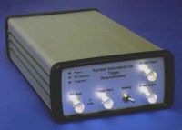 It is often necessary to produce a trigger signal that is synchronised to an RF waveform but occurs at a random time. The Trigger Resynchroniser will produce a low jitter output synchronised to the RF at a time after a trigger signal is received. It is often necessary to produce a trigger signal that is synchronised to an RF waveform but occurs at a random time. The Trigger Resynchroniser will produce a low jitter output synchronised to the RF at a time after a trigger signal is received.
Specifications:
- Trigger Input: >1.5V into 50 ohm
- Trigger Pulse Width: 5ns
- RF Bandwidth: 1MHz - 1GHz
- RF Sensitivity: 300mV peak to peak @ 100MHz, 750mV at 500MHz
- Outputs: 5V into 50ohm, max. rep. rate 4MHz
- Jitter: ca. 10ps rms at 100 MHz

For normalization of images due to laser energy fluctuations
The Online Energy meter is designed for measurement of laser pulse energy. It is capable of measuring the energy of individual laser pulses from a burst and simultaneously with the acquisition of CCD images. The online energy meater may be used as a stand-alone unit or within a complete optical diagnostic system. The simultaneous acquisition of camera images and laser energy increases the accuracy of measurements based on absolute quantification of e.g. LIF signals. Correction for the laser energy variations can be performed by software either online or using batch processing routines.
Features
- spectral range: 248-900 nm (other wavelengths on request)
- wavelength selection by easily changeable filters
- adjustable to typical YAG or Dye laser powers
- repetition rate up to 100 kHz
- doublepulse seperation down to 4µsec pulse to pulse delay
- high dynamic range > 1:500
- repeatability > 99%
- single pulse resolution
- TTL trigger input for synchronization with camera
- data acquisition via USB (optional RS232)
|